FortiGate 90D-POE with FortiAP on 5.4.1
Okay, I feel the need to write this because I just upgraded from FortiOS 5.4.0 to FortiOS 5.4.1 on my FortiGate 90D-POE, and my FortiAP couldn't handle it. I actually had to completely reconfigure my FortiGate from scratch, as I lost everything but console access whenever I would attempt to import my configuration.
Before we begin
- You have two SSID types you can configure
- I chose "Bridge to FortiAP's local interface" for my main WiFi network for two reasons:
- A) This Fortinet doc says "Bridge mode is more efficient than Tunnel mode, as it uses the CAPWAP tunnel for authentication only"
- B) A post in this Reddit thread suggests that tunneled APs use more system resources than a bridged AP
- I chose "Tunnel to wireless controller" for my guest network because I want to apply different levels of UTM to guests than I do to my own WiFi traffic, and if I bridge both SSIDs to the FortiAP interface, I can't apply separate UTM policies.
Step 1: Set up your POE interface
Note: I use the term "bridged wireless clients" here for settings that specifically apply to devices connected to my private WiFi network that will have access to my wired devices through a firewall policy. If you create a guest network (tunnel to wireless controller), it will have its own subnet and DHCP server as explained in a later step. Even without a tunneled SSID, you still need a DHCP server on your POE interface for your FortiAP to receive an IP address.
- Network > Interfaces
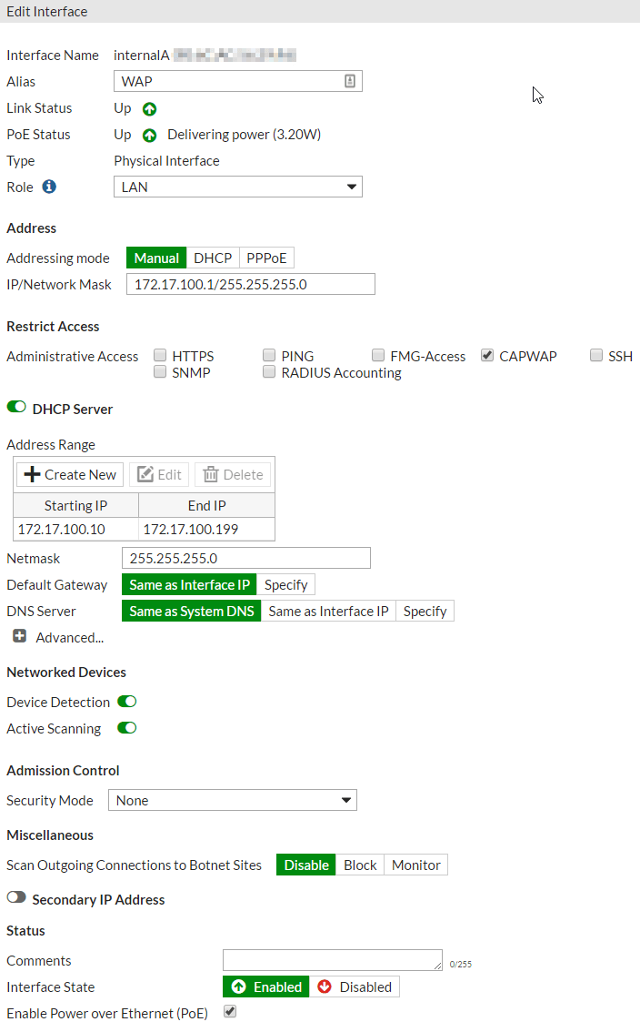
- Edit the POE interface where you connect your FortiAP.
- Select LAN role, Manual addressing mode, type an IP/Netmask that will act as a gateway for your bridged wireless clients (I chose 172.17.100.1/255.255.255.0), select only CAPWAP for administrative access, and create a DHCP server for your bridged wireless clients.
Step 2: Create SSID(s)
- WiFi & Switch Controller > SSID
- Create New > SSID
- Assign a name for the interface (never visible to public), type WiFi SSID, traffic mode "Local bridge with FortiAP's Interface", SSID name (visible to public by default but can be made private), security mode, security mode options, and click OK.
- If you wish to create a guest WiFi network, create a new SSID, choose traffic mode "Tunnel to Wireless Controller," and create a unique IP/Netmask for this subnet, a DHCP server, and finally name your SSID and configure security before clicking OK.
Step 3: Create FortiAP Profile
- WiFi & Switch Controller > FortiAP Profiles
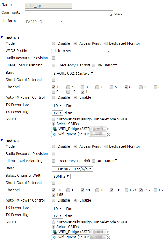
- Create New, assign a name, select your model of FortiAP next to platform (DO NOT SKIP THIS STEP), choose your radio settings, choose "Select SSIDs," and select both SSIDs you created in step 2.
- You are welcome to limit one or more SSIDs to specific bands if you wish.
Step 4: Assign FortiAP Profile to FortiAP
- WiFi & Switch Controller > Managed FortiAPs
- By now, your FortiAP should have received an IP address from the DHCP server on the POE interface you configured in step 1. If it still does not have an IP address, wait. Periodically, click Refresh. Eventually, it will get an IP. This should not take more than 5 minutes, but the time can vary by model.
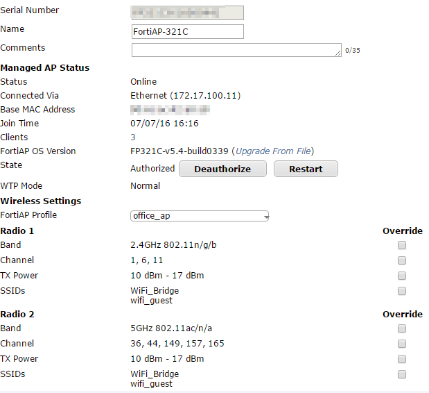
- Double click your FortiAP.
- Assign a name (optional), Authorize the AP, assign the FortiAP Profile you configured in step 2, and configure any override settings as you wish.
- With my FortiGate 90D-POE on firmware v5.4.1-build1064, a Fortinet support representative had me upgrade my FortiAP OS version to FP321C-v5.4-build0339.
- Click OK to finish.
Step 5: Create addresses (subnets) to be used with firewall policies
- Policy & Objects > Addresses
- Create New > Address.
- Create a name for your bridged (private) WLAN, put in the same subnet you created in step 1-1-B, and assign it to your POE interface. Click OK.

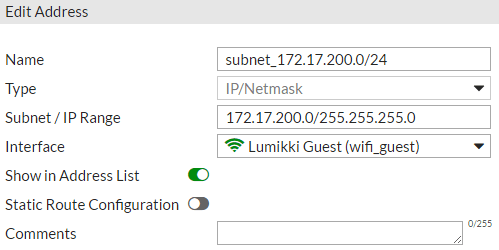
- Create New > Address.
- Create a name for your tunneled (guest) WLAN, put in the same subnet you created in step 2-1-C, and assign it to your guest SSID. Click OK.
- Create an address for your internal hardware switch if you don't already have one!
Step 6: Create firewall policy
- Policy & Objects > IPv4 Policy
- Create New, assign a name, POE interface as incoming interface, internal hardware switch as outgoing interface, address you created in step 4-1-B as source, address you created in step 4-1-E as destination, service ALL, uncheck NAT if selected, ensure "Enable this policy" is checked and click OK.
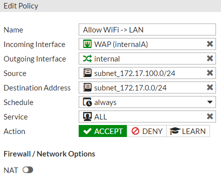 What this policy does: Allows devices on your private, bridged WiFi network to communicate with devices on your internal hardware switch.
- Create New, assign a name, POE interface as incoming interface, internal hardware switch as outgoing interface, address you created in step 4-1-B as source, address you created in step 4-1-E as destination, service ALL, uncheck NAT if selected, ensure "Enable this policy" is checked and click OK.
- Policy & Objects > IPv4 Policy
- Create another policy for the reverse direction (internal to WiFi). See screenshot.
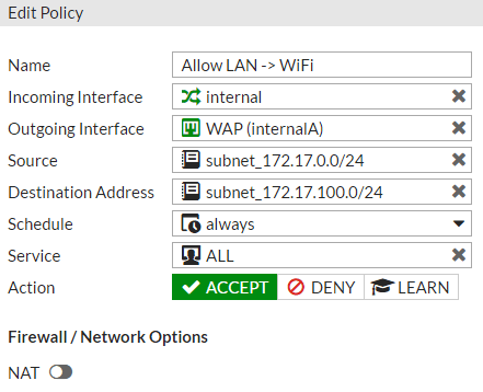
- Create another policy for the reverse direction (internal to WiFi). See screenshot.
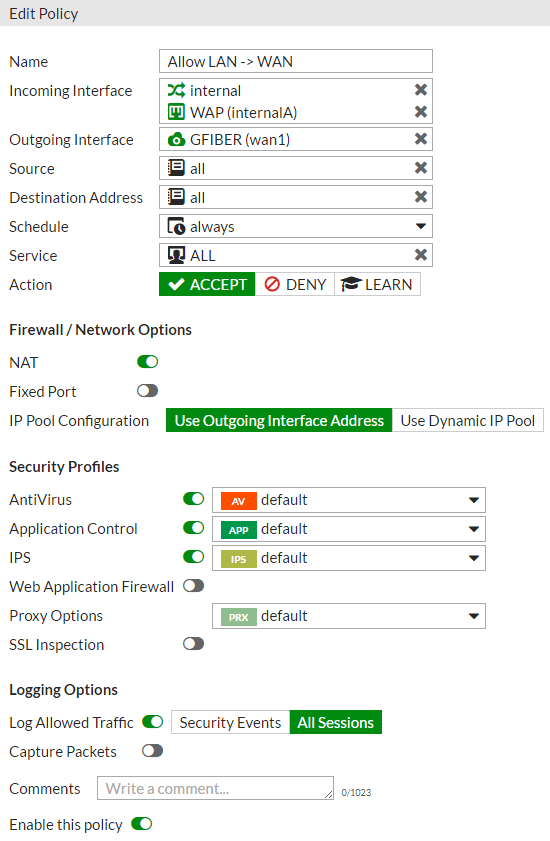
Step 7: Allow WiFi subnets access to the internet using firewall policy
Because you already have a firewall policy that allows devices physically connected to your internal hardware switch access to the internet, you can simply add your POE interface and guest SSID to this policy. Personally, I created a separate policy for my guest WiFi so I can apply more granular control in the future.
Below is my policy for all traffic from my wired devices and private WiFi clients to the internet
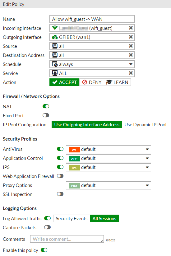
Below is my policy for all traffic from my guest WiFi clients to the internet
That's it! If this helped you, please consider a donation of any amount at all via the PayPal or Bitcoin buttons on the left side of the page. Comments and criticisms are welcome in the comment section.